Category: Smart Home

Step into my Home Automation world where I share information about my #SmartHome and Home Assistant.

  • Smart dog training buttons

    Smart dog training buttons

    At first, it seemed a silly idea to create buttons our new puppy could press to tell us she wanted something. A few weeks later, after introducing these to our new 8-week old puppy Poppy, it seems the idea was far from silly. Poppy has started to learn that something happens when she presses these buttons. What that something is, depends on the button Poppy presses. She has already grasped that one of the three buttons I created allows her to let us know she wants to go out into the garden when the door is closed.

    Poppy pressing the button at 9 weeks old.

    Sure the idea was silly and just an excuse to have some fun. I started off by prototyping with a standard Zigbee button, playing with notifications and the possible languages for text-to-speech messages. I created an amusing character for Poppy’s text-to-speech messages. After trying different languages and adapting some of the spoken words to be more playful and fun, Poppy now had a French voice, and phrases such as “Humans” were read out like “Hoomans”. At this stage of testing, my partner hadn’t vetoed the idea, so I progressed to the design stage.

    Often at this stage, I feel like “Sid”, the antagonist who lived next door to “Woody and the rest of his friends”, and cannibalised toys in Toy Story, mostly because I end up trying to retrofit my crazy projects into something that looks half decent. When I fail, the projects end up in that “special box” we all have, but those that succeed live on another day. While this might make you giggle, there is a serious element to it – that user experience. In the maker space, it is not uncommon to see exposed circuits and wires, etc. For me, that is part of the fun. But it isn’t something I want my final projects to resemble, so I seek simple, intuitive, and good-looking ways to enclose my final projects. This is one of those examples.

    Why does my dog need these?

    She doesn’t. But with a connected smarted home, the things you can do are endless! I’ve grown up with dogs all my life but never had a puppy. With this comes the great responsibility to train her. Rather than bark or scratch the door, I wanted to teach her to use one of these buttons which could notify us that she needs something.

    I guess the solution is no different to panic buttons, butler buttons, and shops or cafes where it would be helpful to get a notification and even leverage text-to-speech when a button is pressed. The options in Home Assistant are truly endless and really provide opportunity to create accessible and inclusive solutions. For example, the solution could easily integrate with lights or digital locks but also loop until something else is done like a door is opened.

    As I made three of these buttons I currently have them set up to notify me when Poppy wants to go play in the garden, one near her lead for when she wants to go on a walk and the other with her food.

    How to make your own pet smart button

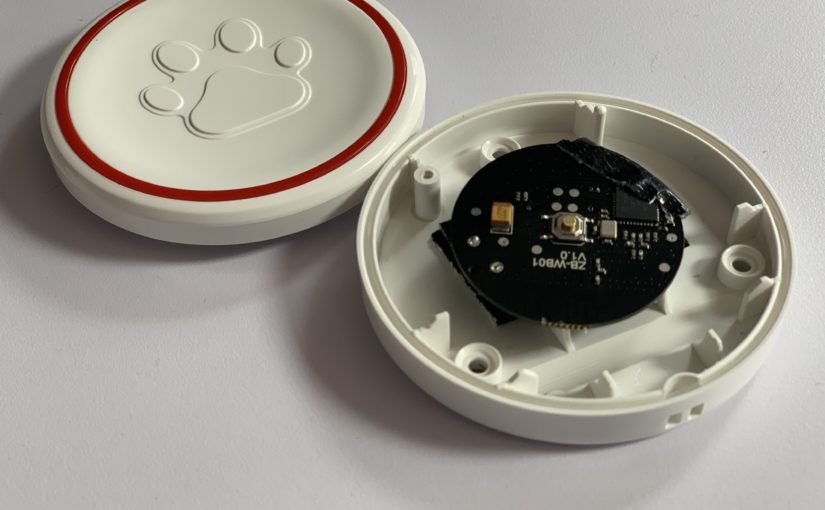
    To make these buttons I brought a set of radio-frequency (RF) buttons. The pack included three nice-looking buttons each with a paw embossed on them and a receiver chime plug. I brought these hoping I could strip them and replace them with my own Zigbee button. Fortunately, the buttons were held together with a few small screws and came apart really easily. Inside was a small RF circuit which was easily removed again by removing a few small screws.

    RF-button remove from its case.
    RF-button removed from its case.

    For the “smart” part, the button, I brought a Sonoff SNZB-01 Zigbee button which I removed from the Sonoff case. This was slightly trickier and needed levering out. For this, I used a plastic ply tool and with a little wriggling was able to remove the circuit from the case. As the case is used to hold the battery in place I used some Gorilla tape to secure the battery to the circuit.

    Sonoff SNZB-01 Zigbee Button removed from its case.
    Sonoff SNZB-01 Zigbee Button removed from its case.

    Then comes the cannibalisation part, combining the new button with the case from the old button. The Sonoff button needs to be positioned in the RF-button case ensuring the button centre is placed in the centre of the case. This is so that when the case is pressed the button can also be pressed. I folded some tape over a few times to raise the Sonoff button slightly. Not over-tightening the screws on the case also provided more play for the button to be pressed.

    Sonoff SNZB-01 Zigbee button inside a case intended to be used by our dog Poppy.
    Sonoff SNZB-01 Zigbee button inside a case intended to be used by our dog Poppy.

    Home Assistant integration

    Home Assistant provides such great flexibility and extensibility. For this project, I created several helpers, which I use to apply the configuration to each button and to integrate each button press with a mobile notification and text-to-speech message which is played out over my Sonos speakers. My Home Assistant configuration is managed through YAML, but the same can be achieved in the UI.

    For each button I created the following helpers and automation:

    Trigger-based template sensor

    The Zigbee button fires events when pressed. I’m using a trigger-based template binary sensor to cause the state of the binary sensor to change when the button is pressed. This provides me with a sensor that I can show in the UI and also capture insights from.

    Note: I have a split configuration where my entities and integrations are defined in folders and YAML files. I wasn’t able to get this template sensor to work like other templates and had to store this in my main configuration.

    Messages

    Both the text-to-speech announcement and the mobile notification message are stored in the input_text helpers.

    Volume and Delay

    To control the volume of the text-to-speech message and the time between the next time the button can be used I created the following input_number helpers.

    Automation

    The following automation calls a text-to-speech script that snapshot my Sonos speakers, groups the speaker’s together, sets the volume and reads then reads out the message before reverting back.

    Lovelace

    Poppy has her own pretty cool dashboard where we track her health, food, and diet as well as her location from her LTE GPS collar. The buttons I made reside in their own Lovelace view in her dashboard.

    As with most, if not all my automation, I leverage helpers to manage the configuration used in the automation as described above for this project. I then expose the helpers in Lovelace which makes it easier to manage and change their values. For example, the volume and text-to-speech announcement and mobile notification are all changeable in the UI via this approach for each of the three buttons I made.

    Using the Fold Entity Row Card I often collapse helpers out of the way. Alongside these helpers, I’ve used the Mini Graph Card to provide insights into when each button has been interacted with over the last day. For those interested in the Yaml for the Lovelace cards, I have shared it here.

    Example Lovelace card for a single button, with helpers and insights in a vertical stack card.
    All three smart pet buttons in Poppy’s Lovelace dashboard.

    I hope this is helpful and other pet owners can see the benefit of these training buttons. If anyone needs me I’ll be training and playing with Poppy 🙌🐶🐾 and now doubt tinkering with some other fun project!
  • Can you IoT an Airwick air freshener?

    Can you IoT an Airwick air freshener?

    This project is one that makes me feel on top of the world but also possibly one of my most craziest IoT projects. I am fascinated with IoT and the point where software interacts with my physical world for example in the simplest form, a sensor programmed to turn a light bulb on when there is motion. I get huge joy from tinkering and exploring how things work but the real satisfaction comes from combining connected sensors, data, automation and machine learning and of course learning myself. This project was no exception.

    We’ve all most likely been into a public restroom somewhere and had the automatic air freshener trigger and possibly even make us jump out of our skin when it does. These units typically run on a schedule and spray some kind of air freshener into the room. Some are even a little smarter and trigger when there is motion in the room. Well I have a number of air fresheners like these in the house and sure they’re not necessary but I like them and they smell nice. What I don’t like is how they continue to work when I’m not in the room and even not in the house. This is entirely wasteful and not very smart. And well my house is smart so get with the programme! The other problem is if you’re like me and find it hard to sleep sometimes the noise of them spraying throughout the night is annoying and likely lead to me saying to myself was trying to get to sleep “I wonder if I can make these things smart“. I’ve likely fallen asleep as this stage and forgotten about the crazy idea, but clearly this one time I didn’t, so here I am writing about how to IoT Airwick air fresheners. Let’s consider a smart air freshener and how it would work if it wasn’t triggered by a manually.

    Motion. Rooms can be busy so triggering with each motion event would as wasteful as it spraying every 15 minutes now. But we could use motion in combination with when the air freshener last sprayed to ensure it only sprays every 30 minutes for example.

    Alarm state. If my house alarm is armed then that is a good sign I’m not home so the air fresheners shouldn’t work. This could also prevent them from working when in night mode but there is, of course, one the exception to that, the bathroom!

    Room based triggers. In the living room, if the TV is on or the sofa is occupied then the room is in-use. In the office, if my workstation is unlocked then I am likely working and the room is in-use. If my toilet is flushed and the bath or shower is in-use then that is a great indication the bathroom is in use. And yes, I’ve IoT’ed my toilet! Then there are exceptions like if I’m having a bath I probably don’t want it to be triggered as it would mess with my Zen.

    Spray interval. The unit provides some control over the frequency the air freshener sprays but this is limited to 9, 18 and 36-minute intervals. Why these intervals I don’t know but I’m sure Airwick have their reason. It would be useful to replicate this and allow longer intervals between sprays.

    Sensors. Throughout my house, I have a large collection of sensors and in a truly connected world, these should be considered too. For example, when the alarm is unarmed after a trip away the air fresheners could be sprayed to create a welcoming smell. If windows are open then I’d rather have the fresh air than the air freshener so don’t have them spray.

    Voice. In an inclusive world, voice assistants are increasingly used to perform tasks that ordinarily might have been out of reach for some people.

    So considering all of the above I decided to accept the challenge and IoT’ed my air fresheners. But with all these crazy ideas – I wasn’t going to compromise on the aesthetics. The look and feel could not be compromised. Let me walk you through it.

    Ingredients:

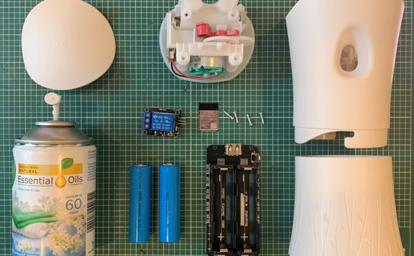
    Airwick Air Freshener

    The Airwick air freshener device is pretty discrete. It contains a can of the air freshener of your choosing and two AA batteries. Behind the scenes, there is a 3v motor which when powered, powers gearing that creates sufficient force to push down the nozzle on the can of air freshener. Notice the red plunger gear is only two-thirds round. This prevents the gearing from forcing the aerosol can to spray continuously and it runs out of gear. When the motor is no longer powered the gearing reverses from the return force of the nozzle of the can of compressed air freshener.

    Gearing and the plunger from inside an Airwick air freshener.

    The build

    This was quick to build out and I had a working air freshener activated through my NodeMcu in about 15 minutes.

    The components connected for testing.

    I planned to use a smaller ESP32 dev board but for this prototype, I’ve opted to use the standard board for ease of access. I made a few alterations to the plastic insert in order for me to place the components inside.

    All the components to make an IoT Air Freshener packed away inside.

    I also planned to use larger batteries but will need to 3d print a housing for that so for this prototype I housed the battery discretely on the back for ease of access and space reasons.

    The battery is discretely located on the back for the prototype.

    ESPHome

    In order to operate my air freshener automatically, I need something that I can programmatically control from Home Assistant. To provide me with the compute for this IoT project I turned to my trusted and favourite ESP32 NodeMcu board flashed with ESPHome. The ESP32 NodeMcu is powered from a battery and is connected to a relay. This relay allows a circuit to open and closes which then activates the motor and gearing inside the air freshener.

    Fritzing wiring diagram.
    Fritzing wiring diagram

    In 10 lines of configuration, I was able to create a switch that operates that relay and that’s it. It is as simple as that. To turn the switch on and off you need an interface. ESPHome provides the ability to do this through a web UI, MQTT or in my case through integration with Home Assistant. In fact, Home Assistant auto-discovers ESPHome devices so the switch I defined in my configuration is immediately available to use.

    To preserve the battery I decided to use the deep sleep and MQTT component in ESPHome. This allows me to wake the device, check the state of a MQTT topic. It then either triggers the air freshener or goes back to sleep depending on the state of that MQTT topic and save battery power.

    Home Assistant

    The brain of my house Home Assistant handles all the integration with ESPHome, other sensors and the home automation logic.

    ESPHome air freshener switch integrated with Home Assistant

    I won’t go through all of the different automations I have created to work with my new-fangled smart IoT air fresheners but instead, I’ll show you an example that in part is the most applicable for an air freshener. My bathroom air freshener. That particular air freshener is triggered when my IoT toilet is flushed and as automations go is the coolest toilet air freshener automation you will likely to ever see!

    For me, the data is as much fun to play with and analyse as the tinkering with all the hardware. To provide me with additional data points that I can study, I added a counter that increments each time the unit is sprayed and a date sensor to store when the air freshener was last replaced.

    To preserve battery life the ESP board goes into a deep sleep and wakes every few minutes to check if it needs to trigger the air freshener. This is achieved using an MQTT topic. I created an MQTT switch that is enabled when a binary sensor is on. This switch triggers the air freshener to spray and is reset before ESPHome sends the device to sleep again.

    Alexa – beast-mode level five-thousand!!!

    We all know there can be those moments when a little fresh air is most welcome. For those situations, I’ll leave you with this.

    Alexa, it’s stinky.

    This uses a custom component for Home Assistant called alexa_media_player. An Alexa routine is created to listen for that sentence which then set the brightness level of a virtual light created in Home Assistant to a particular level. Then an automation in Home Assistant is triggered. It checks which room Alexa was used in and then activates the air freshener a few times in that room.

    One thing I have noticed with Alexa routines is that I’ve always had to keep the wake sentences short and not complex in order for them to be picked up by Alexa. For example, for this I started with “Alexa, it is stinky in here” but her response would be “Sorry, I don’t know that one”. Instead, I simplified the wake sentence to “Alexa, it’s stinky and “Alexa, it smells”. This could be taken a step further and a routine could be used to activate all the air fresheners like “Alexa, freshen up the house” for those moments when you have someone special coming over!

    Screenshot of my it is stinky routine in the Alexa app.

    Closing thoughts

    This really could not have been made any easier and that is down to two great projects Home Assistant and ESPHome. I strongly recommend that if you haven’t explored Home Assistant, ESPHome or ESP32 NodeMcu for tinkering you give them a try.

    From this picture, it is impossible to tell that this Airwick air freshener has been IoT’d.

    I started by saying I would not compromise on the look and feel of the unit and hopefully the above demonstrates this. There are other benefits to this madness. My friends won’t freak out from the sound of the air freshener spraying nor think I think they smell! The air freshener will last longer and because I converted the batteries I can recharge them. I’ll be able to work out when the spray needs replacing from the data. Oh and I’ll be able to get off to sleep without hearing that clicking noise and troubling myself with such crazy ideas like this. For now at least!

    So while I’ve made a few jokes in this article and had lots of fun along the way, the point I want you to take away is that ideas can become reality. Crazy to you might not be crazy to someone else. Let your mind run away and be creative. The growth and learning opportunities are endless.

    I 💕 my Home Assistant

  • Turn lights on and off when Windows 10 is locked or unlocked

    Turn lights on and off when Windows 10 is locked or unlocked

    Like many, I have smart lighting throughout my house. This includes my office and desk. Behind my beautiful ultrawide monitor, I have a 3m Philips Hue strip which helps add some peripheral light and softens the glare when using the screen. I use scenes to adjust the level of white light towards early evening, but I’ll save that for another day. While I can manage the lights in the room based on motion, I wasn’t doing anything with my monitor lights as I might have been working, but the room could have had no movement. This would have resulted in the monitor lights turning off and would have been frustrating, so I decided to integrate whether my workstation is locked or unlocked or not with Home Assistant.

    My desk lights turning on when I unlock my Windows machine using Home Assistant

    Previously I had a PowerShell script that I could run that would hit the Hue API to toggle my lights on or off but since I have moved away from my Hue bridge this no longer works plus it wasn’t automated, but this was a good starting point. The sysadmin in me remembered there was a trigger in Task Scheduler that would be a task when the workstation was locked or unlocked, which gave me the trigger for my Home Assistant integration.

    Picture of the trigger screen in Task Scheduler showing the different triggers that are available.
    Workstation lock/unlock triggers in Task Scheduler

    The next part was talking to the Home Assistant to perform service calls such as light.turn_on or scene.turn_on. Fortunately, I know Home Assistant provides great extensibility and has a fantastic rest API, so that was Home Assistant. This just left the process to call the API. For this, I wanted to stick with PowerShell as it is very versatile and I use it all day long anyway.

    I had a prototype working very quick, but I wanted something more modular and parameter-based to use for other things. This is when I took found Flemming Sørvollen Skaret’s Home Assistant PowerShell Module. His PowerShell module is awesome and really handy. I was off and running with it within minutes. So I decided to leverage this module in my Task Scheduler automation. And that was that, but I still had to hook it all together.

    • 2 x Task Scheduler Tasks – triggered when the workstation is locked and unlocked
    • 1 x VBScript to launch our PowerShell script so it is hidden
    • 1 x Flemming’s Home-Assistant PowerShell Module
    • 1 x PowerShell script to call the Home Assistant API
    • 1 x Home Assistant long-live token
    • 1 x entity in Home Assistant (a light, scene or input_boolean for example)

    Task Scheduler

    First I created two tasks in Task Scheduler. One for when the workstation locks and the other for when it is unlocked. When these tasks are triggered, they call a VBScript with some parameters. Yes. An actual 1900’s VBScript in 2020. For the life of me, I could not stop or prevent the PowerShell console from flashing up. I’m a UX nerd, and this wasn’t acceptable for me. I spent way too long on trying to solve this before I reverted to this well-known workaround of using WScript to execute the PowerShell script silently. These have been exported from Task Scheduler and therefore can be imported straight back in obviously correcting usernames and paths.

    You will notice on line 46 above calls a common TaskSchedulerLauncher.vbs script along with the path to a ps1 file and the parameters to go with it wrapped in double-quotes.

    Are you using a battery-powered device?

    Geert van Horrik (@GeertvanHorrik) kindly pointed out that if you are using a battery-powered device like a laptop or a tablet you will need to change the conditions so the task runs when on battery power.

    Power settings for a task in Task Scheduler

    VBScript

    Having to use the VBScript is annoying but not as annoying as the PowerShell console flashing up each time I unlocked my workstation. It calls PowerShell.exe and our script while also setting the window style to be hidden.

    PowerShell

    In order to interact with the Home Assistant API you will need a long-lived token. You can create one in the Long-Lived Access Tokens on the profile page (http://localhost:8123/profile). Be sure to name it something sensible and meaningful.

    The token and information about my Home Assistant instance are stored as variables in the script. The service I want to call such as light.turn_on, scene.turn_on and input_boolean.turn_on and the entity_id (input_boolean.james_desk) are passed to this script as parameters.

    Additionally, as the PowerShell script contains the token to Home Assistant I store the script within my profile and limit the permissions to the file to just myself.

    Home Assistant

    I started off by just toggling the state of my monitor light but I shortly realised I could achieve more if I knew my workstation was unlocked so I created an input_boolean.

    I toggle the state of this each time my Windows 10 machine is locked and unlocked. This means I can do more than just turn my lights on or off. I use this input_boolean in my motion automation which prevents my room lights from turning off if my workstation is unlocked (no more crazy waves). It also stops my Dyson fan from oscillating and directs it towards my desk and changes the speeds if the temperature is above a threshold. I can also choose route TTS notifications through to my desk Sonos speakers or HTML5 notifications to just my workstation.

    Best of all with Windows Hello I just sit down at my desk, and Home Assistant handles everything else because it knows my workstation is unlocked and the chances are I’m working or tinkering with something at my desk.

    I’ve also used the same PowerShell method to create a set of quick actions that I can call from buttons on a Home Assistant Stream Deck board where I can call my favourite playlists and scenes. I’ve also created some TTS scripts to announce and nag when chores need to be done or when it is dinner time! I think I’ll save that for another post!

    I 💕 my Home Assistant

  • Framing an #IoT thing of beauty

    Framing an #IoT thing of beauty

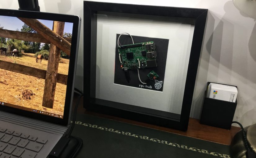
    A picture can tell a thousand words. That’s just what I wanted to achieve by placing my Raspberry Pi into a picture frame. This all started with a long trip to IKEA over the weekend. One of those trips where you get to the car and realise you have way too much to fit it all in the car. During this long trip, I spotted a thick picture frame. My mind jumped at the thought of placing a working Raspberry Pi within it. Well, this evening I decided to give it a try and went about trying to house a Raspberry Pi in the picture frame and succeeded.

    I researched how others might have tackled this. My searches returned examples where people have made a digital picture frame as opposed to housing or framing a Raspberry Pi in a traditional picture frame. Bizarrely the one example I did find, Digital PI-cture Frame by David Park was from IKEA Hackers. Great minds! This, although some years old was what I had pictured in my head.

    IKEA Ribba picture frame

    I love my tech and whilst I appreciate the clean, tidy and organised side of life. Sometimes I hate hiding things away too. This isn’t just any Raspberry Pi, this is one that is the hub of our home automation. One that should be out on display for everyone to see.

    I was really torn whether I should house a Raspberry Pi 3b or a Raspberry Pi Zero within the picture frame. They are both absolutely beautiful and remarkable devices. In the end, I decided on the Raspberry Pi (RPi) 3b as it is such a significant device to our home. I may add another frame to house a RPi Zero for another project in a few months. For now, the frame currently sits on my desk but I plan to hang this on a significant wall in the house and make a feature of it including some internal lighting.

    A picture frame as a Raspberry Pi case

    The list below is a summary of bits I used:

    • Picture Ribba frame – IKEA £3.50
    • Black backboard – cut from a recycled notepad
    • Mounting nuts/bolts – taken from a spare Raspberry Pi case

    OpenHab

    For those wanting to know what that other bit is that is included in the picture frame. It’s a RF transmitter (315MHz). This RPi runs OpenHab where I have some rules that trigger my projector blind to come down or go back up when using my Logitech Harmony remote. Personally, I think the picture frame looks better for having something alongside the RPi rather than having it sat there by itself. I’ll have some more posts on this topic very soon!

    My Raspberry Pi at work sending RF codes
  • Battery powered portable Sonos Play:1

    Battery powered portable Sonos Play:1

    Well my Sonos Play:1 warranty is now void less than 24 hours after being delivered. This isn’t going to be one of those sexy extreme unboxing it instead of my personal experience in making my first Sonos speaker more portable and more accessible by powering it via USB. In short, I stripped apart a new Sonos Play:1 speaker and added the circuitry to power the unit using USB.

    https://www.youtube.com/watch?v=bJs629jfpZs

    I love music and listening to a few stations on the radio. We have radios scattered throughout the house. This tends to result in me not listening to any of my music or playlists because of the convenience of having a radio in almost every room in the house. I’d say I listen to music or the radio far more than I watch TV. Sonos speakers have always been a ‘thing’ on my ‘for the house’ list and after experiencing them while visiting some friends recently (who highly recommended them mind) I decided to buy a Play:1 and give Sonos a try!

    Battery powered Sonos Play:1
    A Sonos Play:1 you can move anywhere you like using a portable battery.

    I’m now in love with Sonos speakers and question why it has taken me so long to buy one. They’re amazing!

    The build quality is great (inside and out!) and more importantly the sound quality is superb (okay so maybe the bass is a bit overdriven on the Play:1 which causes excess bass driven vibrations at times). They kick the ass out of any of my other Bluetooth speakers. I will no doubt buy more Sonos speakers to have throughout the house but until then, I just have the one Play:1 to play with. Which is why I wanted more flexible to move this Sonos Play:1 around the house – from the study to the kitchen to the bathroom, garden and bedroom. This is the reason for this post.

    I have plenty of sockets I could power the Sonos Play:1 from both inside the house and out, but I felt USB powered comments would give me the greatest flexibility to move it around. We even have those power outlets with USB included in them which this was another reason to add USB power. Plus I just love tearing things apart I guess.

    Struggling with power with volume above 80%

    So what gives, nothing other than volume at the top end. I have the same issue with the power consumption of the Play:1, if the volume is above 80% the unit requires more power than what can be supplied. This causes sound distortion and is demonstrated in one of the videos that inspired me to do this hack in the first place (Sonos PLAY:1 USB powered, how-to!!). Anything above 80% volume is really kicking it in the first place so I’m not troubled by this compromise.

    The wireless performance of a portable Play:1 is really impressive. I moved it throughout the house and garden and I’ve yet to experience the Play:1 stop streaming due to connectivity issues. This in part is down to the quality of my home network but credit, where credit is due Sonos, has done a great job here. When I travel, I travel with my trusted MiFi device. It replicates my home SSID. This means any of my devices connect just like they would at home and don’t need any more config. I could, therefore, take my Sonos speaker with me when on the road, staying away or travelling, assuming you have an amazing data plan or a music library accessible by the Sonos speaker!

    Hacking apart the Sonos Play:1

    I won’t detail the specific steps involved, in part, I don’t want to be hit with the bill for replacement Sonos speakers. But also because I managed perfectly by watching two YouTube videos – Sonos PLAY:1 USB powered, how-to!! and Howto open Sonos PLAY:1 – Part 1. Happy for you to reach out to me for any questions or help if you’re trying this out yourself.

    Basically, I took the Sonos Play:1 apart, carefully pulled the circuitry out. I then added a micro USB socket and step up converter that takes the 5.5V current from a USB input and increases it to 24V to power the Sonos speaker. The only thing I did differently from these videos was that I included the micro USB socket. This makes the cable detachable like most other devices. I intend to use the Play:1 in various locations and didn’t want to lose the figure eight mains power lead nor have a USB cable attached all the time. Win, win!

    Inside a Sonos Play:1
    Step up converter fixed inside a Sonos Play:1

    What I used to pull this off.

    1. Micro USB PCB board (remember power out from a USB requires pin VCC to Positive and GND to GND)
    2. Dremel used to drill and shape the hole used for the micro USB socket on both the speak enclosure and the speaker cage cover
    3. Power step-up converter to increase the USB power from 5V to 24V
    4. 5.5mm USB to a power socket for testing power from a USB power source
    5. Solderless 5.5mm female socket, again for testing with the above lead
    6. Glue gun – the cables and terminals inside the Sonos Play:1 are very well insulated with what appears to be a PVA like glue gun insulation – I did similar with my soldering joints and used the glue gun to secure the step-up converter
    7. Soldiering skills
    8. A good set of Torx screwdrivers
    9. A Jenga like a mind to work out the best place for the extra step up converter component and micro USB socket while still being able to put it all back together again
    10. Dappy looking zip bag to enclose the speaker and battery and make it even more transportable and big buggy pram clip – for example hanging the Sonos under the garden parasol
    11. USB power source or a USB battery and micro USB lead to make your Sonos speaker portable – my current battery is a Repower PB19 a 4.5amp 17000MaH
    12. Heavy duty Velcro to stick the battery to the speaker
    Portable Sonos Play:1
    Portable Sonos Play:1 powered with a USB battery pack in front of my fire place.
    Sono Play:1 with battery attached using velcro
    Sono Play:1 with the battery attached using Velcro

    My portable Play:1 will live on.

    I completely get why you would have a Sonos in almost every room. Until a time when I do, this solution will suffice perfectly thank you. Once I am fully Sonos’ed in every room, my Portable Sonos Play:1 will live on with its dappy looking pull string bag.

  • Philips Hue LED kit extension lead hack

    Philips Hue LED kit extension lead hack

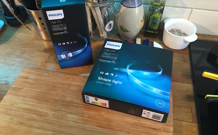
    With most of the house HUE’d up, I thought I would add Hue lighting under the cupboards in our kitchen. I love cooking but am often frustrated because of the poor lighting on the work surface in the kitchen. The trouble is the Philips Hue LED kit is only available in two sizes, the 2m main kit and in 1m extensions. Our kitchen cupboards are split in two by our cooker hob extractor. This leaves me with cupboard lengths of 1.4m and 1.6m. I did some research but could not find an extension lead for the Philips Hue light strips so rather than shedding out on two kits, I decided to hack together a solution to create my own extension lead.

    Philips Hue lightstrip extension lead hack
    Philips Hue lightstrip extension lead hack

    Appreciating the risks and the potential cost of replacement involved if I failed, I took off and carefully hacked my own extension lead together. Below is a list of what you’ll need to do this yourself and the steps involved to make your own extension lead for your Hue light strips.

    What you’ll need to hack your own Hue light strip extension lead together

    • Philips Hue Personal Wireless Lighting 2 m Lightstrip Plus
    • Philips Hue Personal Wireless Lighting 1 m Lightstrip Plus Extension
    • Wire cutters and a good wire stripper
    • Heat shrink to protect any exposed cables once we finish
    • Soldering iron and solder to join the extension lead wires onto the Philips Hue light strip
    • The desired length of cable (this will be your extension) – I couldn’t find a wire with six cores so used two five metre lengths of four core wire. Far less attractive but good enough for the hack this time around
    • Optional connector terminals and a crimp tool (male/female spade terminals) – these allowed me to pass the extension lead through backs of my cupboards more easily
    • Optional staple gun to tack the leads to the cupboards.
    The tools you'll need to create the extension lead.
    The tools you’ll need to create the extension lead.

    The steps involved…

    1. Plan and test the placement of your light strip and where you will attach the extension lead.
    2. Work out the route of your extension lead – in my case I went through the backs of the cupboards and then up and over the top of my extraction fan. This required a few holes to be drilled into the cupboards.
    3. Prepare your extension lead. Strip and tin each of the wire with the soldering iron.
    4. Decide if you will include a connector to allow you to separate the extension lead from the light strip. If you are going to add one, cut, strip and crimp the wires with your connector – in my case I used a set of spade terminals.
    5. Grandad always said measure twice cut once – so run through your placement and cabling route once more.
    6. And don’t be silly – remember to power off the light strip before the next step!
    7. Cut the light strip at the nearest cut joint because this is where we will solder our extension lead wires onto.
    8. Carefully cut back some of the outer plastic on the light strip so that you can solder your wires onto the terminals. Make sure you don’t forget to include some heat shrink to protect these joints once you have terminated the wires.
    9. Test the lights work correctly before fitting in your desired place.
    10. Tip! If placing under cupboards, place the light strip at the back for the best effect.
    11. Optionally use a cable staple gun to tack the extension lead throughout its route to make it extra secure.

    Grandad always said, measure twice cut once.

    This slideshow requires JavaScript.

    Product improvement idea

    Philips could avoid this problem altogether and avoid any hacking at all. Firstly they should offer an official 6 core extension lead. Secondly, they could alter the cut joint they include at various points throughout the light strip. Making each cut joint made up of a male and female connector under the plastic. To extend the lightstrip you would then simply cut over the joint and use the official Philips Hue light strip extension lead. The extension lead would have a male and female connector at each end, allowing you to simply connect it to the section you have just cut.

    extensionlead

    That aside, kudos to the Philips team for creating amazing lights and for placing cut joints throughout the light strip. This made my hack so much easier to pull off.

    The Philips Hue light strip at it's brightest.
    The Philips Hue light strip at it’s brightest.

    I’m really impressed with the outcome of the Philips Hue LED light strips and my custom extension lead hack. I hope you find this article helpful and it inspires others to extend Hue light strips more easily. This post is part of my home automation series. If you liked this hack, be sure to check out some of my other home automation hacks.